
Adding Spotlights to MGTF - wiring help needed pretty please!


Replied by Malakite on topic Adding Spotlights to MGTF - wiring help needed pretty please!
Posted 1 year 4 months ago #212060Reply is in GREEN.
Small green connector with 4 wires is, by explanantion of the seller, connector of generic switch which you will not use at all (so you can forget about it). (OK. But do I not need to connect the larger correct fitting green connector, so the wires that are going into the smaller one, as these come from the 'relay' loom?) This small green connector and its wires coming from relay are/will be parallel surplus to your larger correct fitting green connector when all its new wires are connected to appropriate places.
I meant that I must wire the new connector into the wires coming towards the small connector no? I ask as these wires are coming directly from the relay?
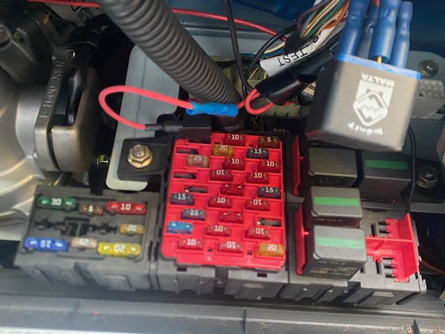
Red/White wire with "C-shaped" connector which goes to in-line fuse is power wire for the fog lamps. That wire needs to be connected to car battery or any strong power point with large fuse capable to power front fog lamps - in accordance to seller. (Do you have any suggestions? I'd need to massively extend this back if going directly to the battery, and if I did - does it need an additional fuse, or otherwise do you have any suggestions as to where I could fix it to i.e. another wiring loom under the dash?) Good alternative is fuse box under steering wheel. You cannot tap it to existing loom because power load of fog lamps can be too much and we do not want to make fire. I do not know which fusebox you have - meaning is your car MG TF mk1 or mk2. Picture of your fusebox under steering wheel would be good. Picture attached. Do let me know where I should be attaching the red wire there please

Black/Grey wire with "C-shaped" connector is earth wire for above mentioned relay trigger coil (trigger circuit in accordance to seller). That connector needs to be connected to nearest earth point. Since I am not with you in car I cannot point you where to connect it at this moment. (ok so I can always earth that to any part of the car then??..) You can earth it to any part of the car, BUT that part of the car must not have any paint on it, since paint is isolator. You need bare metal. Good point is again in fusebox under steering wheel. I have just taken pictures of under the steering column for you.. Also a shot of the centre consule as I am trying to see if you know of any particular areas that I could attach the earth to? Worse case I presume I just drill and screw in somewhere out of the way?
i would like one big thing to be done, that is, your front fogs switch to be tested and see if pinout is assumed correctly - do pin 1 has continuation to pin 4 when switch is pressed, and will switch lights glow when power is applied to described pins. Without this test we are guessing and problems might occure if we assumed wrong. (OK - what may I ask, is the best way of testing that? So sorry to be so dumb when it comes to electrics!) I have a standard current light/screwdriver, and also a multimeter, although the latter is not with me at the moment it's 3 hours drive away!) For this you need a multimeter, but if you are not good with it, better to find someone who is to make these tests. I will bring my multimeter down with me on my next trip (the car is in a car park at a friends house 3 hours drive from my house - I am staying with him a couple of days a week to work on it..) If you could give me in very dumbass terminology, how I check the circuit between pins 1 and 4 of the switch itself I mean? Is it a case of one needle on one pin and the other on the other??
Thanks as always boss
Please Log in or Create an account to join the conversation.


Replied by Roverlike on topic Adding Spotlights to MGTF - wiring help needed pretty please!
Posted 1 year 4 months ago #212064Please Log in or Create an account to join the conversation.
Replied by Malakite on topic Adding Spotlights to MGTF - wiring help needed pretty please!
Posted 1 year 4 months ago #212069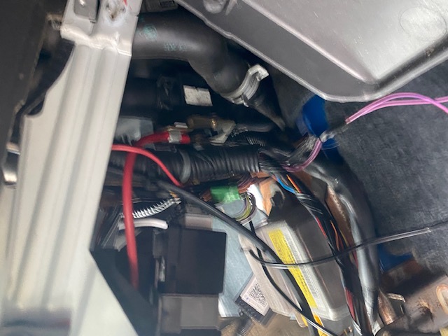
Please Log in or Create an account to join the conversation.
Replied by TA22GT on topic Adding Spotlights to MGTF - wiring help needed pretty please!
Posted 1 year 4 months ago #212073You amaze me every time you post.
Please Log in or Create an account to join the conversation.
Replied by Roverlike on topic Adding Spotlights to MGTF - wiring help needed pretty please!
Posted 1 year 4 months ago #212074I meant that I must wire the new connector into the wires coming towards the small connector no? I ask as these wires are coming directly from the relay? Only one wire will be tapped from that connector, in accordance from the seller, nothing else.
Regarding your picture of the fusebox - I already see that you have one "power thief" on fuse number 1. Who did that job? This question is important because you need another one of the same, for your Red/White main wire.
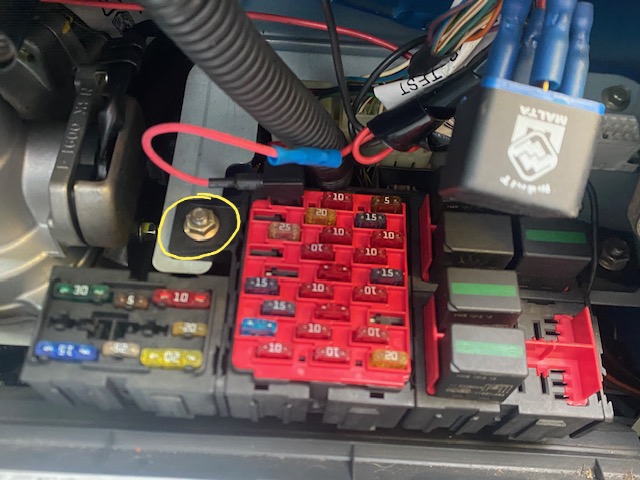
As ground loint you can use one of the nuts of fusebox holders circled in yellow. Note that you need firm metal to metal connection, so best to secure it on the other side where bolt touches metal frame of the fusebox holder.
Please Log in or Create an account to join the conversation.
Replied by Malakite on topic Adding Spotlights to MGTF - wiring help needed pretty please!
Posted 1 year 4 months ago #212087Good spot re: Fuse 1.. I have zero idea - I don't even know what that is for.. I presume it's for the transistor thingy (black box sligtly to the right on the pic??) no clue what thats for.. I will trace the wires tomorrow and take a look.. I wonder if it was for an old stereo or something that's no longer in use? It has no fog lights fitted of course, as I am trying to do this myself as you well know lol!
Also, I will google how to check connections on the main switch.. I will taje it out the car and take home with me to try and work with my multimeter!
Please Log in or Create an account to join the conversation.
Replied by Roverlike on topic Adding Spotlights to MGTF - wiring help needed pretty please!
Posted 1 year 4 months ago #212095Now for the main Red/White wire. You need to purchase one mini blade "power thief" with 2 mini blade fuses rating 15 amps. These 2 fuses go into "power thief". (Note that you can actualy use only one fuse rating 15 amps since you are putting this adapter into empty slot - you will see later in the text - but which position of the fuse within the adapter - upper or lower - can be left empty depedens of manufacturer of the adapter). Picture below:

Then you need to cut C-shaped connector from Red/White wire and take off isolation from the end of the wire in legth of half of inch or less. Take first less and see how wire fits into ble bullet connector of the "power thief". You should not see any bare wire outside of the bullet connector. If satisfied you need to crimp bullet connector firmly in order for the wire not to be able to come,out easily.
Such prepared "power thief" goes into empty position on the fusebox for fuse number 5 as per picture below:

That position in the fusebox is prepared for front fogs.
NOTE: Do not leave "power thief" within fusebox until whole work on the wiring is finished, to prevent short circuits and possible fire.
I made some thinking, and concluded that we can use three wires from obsolete small green connector for the larger correct green connector, but we will come to that later.
Are you comfortable to do the work described above?
Do you see light blue connector from rear fogs switch, near by? Rear fogs switch is one switch apart from front fogs switch in your picture below. Can you post a picture of it?

Please Log in or Create an account to join the conversation.
- Notanumber
-
 Offline
- Senior MGer
-

Site Supporter
- Posts: 2375
- Thanks: 504
Replied by Notanumber on topic Adding Spotlights to MGTF - wiring help needed pretty please!
Posted 1 year 4 months ago #2121012003 MG TF 135 sunstorm
1979 MGB GT
Previously:
2002 115 TF + 1998 118 MG F
Please Log in or Create an account to join the conversation.
- Airportable
-
 Offline
- Master MGer
-

Site Supporter
- Posts: 3675
- Thanks: 912
Replied by Airportable on topic Adding Spotlights to MGTF - wiring help needed pretty please!
Posted 1 year 4 months ago #212102M
Please Log in or Create an account to join the conversation.
- Notanumber
-
Offline
- Senior MGer
-
Site Supporter
- Posts: 2375
- Thanks: 504
Replied by Notanumber on topic Adding Spotlights to MGTF - wiring help needed pretty please!
Posted 1 year 4 months ago #2121122003 MG TF 135 sunstorm
1979 MGB GT
Previously:
2002 115 TF + 1998 118 MG F
Please Log in or Create an account to join the conversation.
Replied by Roverlike on topic Adding Spotlights to MGTF - wiring help needed pretty please!
Posted 1 year 4 months ago #212124
Since you have three free wires with terminal attached for them to go into correct green connector, I would suggest to put them in this order:
Pin 1 - Red
Pin 2 - Yellow
Pin 4 - Green
Pin 5 is already occupied with Black wire.
NOTE that you need to take car how you put terjinal into connector since if you put it up side down it will not work and you may jam the terminal in connecotr so will be hard to rectify the error.
Although I am not advertising use of scotch locks, and I am against use of them, I think that in this case it would be the easiest way to use them. I would do it with soldering iron and heat shrink tubes, but I am few thousand miles away, so cannot do it myself.
So you will need to purchase 4 scotch locks of appropriate size in accordance to yoir wires diameter. If you buy too small, you can cut the wire, if you buy too big, there will be no connection.

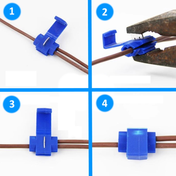
From obsolete small green connector we will use three wires:
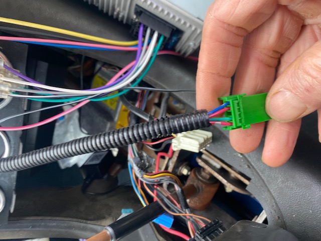
in following order:
Small connector Red/White (pick one from 2 available) wire you should scotch lock with Red wire on big connector (Pin 1)
Small connector Blue wire you should scotch lock with Black wire on big connector (Pin 5)
Small connector Green/Yellow wire you should scotch lock with Green wire on big connector (Pin 4)
This leaves us with only one remaining wire on correct green connector - yellow on on Pin 2.
On Light Blue connector I ask in previous post for rear fogs, you should have Red/Black wire in position of Pin 2.
Now you should scotch lock remaining Yellow wire from correct big connector to that Red/Black wire from light blue connector of front fogs.
Well, if everything is connected as advised you can connect correct big green plug into switch and you can put big red power thief connector back in fusebox in order to test if front fogs work.
Please Log in or Create an account to join the conversation.
Replied by Malakite on topic Adding Spotlights to MGTF - wiring help needed pretty please!
Posted 1 year 3 months ago #212201Roverlike (my hero!) I am back at home in Norwich at the moment and not back to Kent where the car is, until next week now sadly.. but I shall start testing the switch here and feed back to you.. I am going to print this out too so I have everything to follow whilst away from the screen!
Notanumber - yes of course - happy to help someone else seeing as I am getting so much help... will take pics and send to you net week!...
Roverlike - is this a good time to mention to you that I also purchased an electrical 'boot' switch for the car too, which I am wondering if I should be installing at the same time, seeing as the inside is in bits at the moment anyway lol... I can post a pic of it it to show you
Please Log in or Create an account to join the conversation.