
MGTF Door lock drop rod linkages


Connecting the key operated lever arm to the lock actuator is a rod. At the top end of the rod where it locates within the arm of the extension on the barrel is elastomeric bush.
At the actuator end the bush is part of the actuator itself.
Does anyone know of a source for the elastomeric item that fits into the hole in the lock barrel lever arm. It is probably part of the rod itself.
I could sensibly do with a replacement (bush or complete arm). This is to reduce unwanted freedom of movement when using the key.
At the actuator end the bush is part of the actuator itself.
Does anyone know of a source for the elastomeric item that fits into the hole in the lock barrel lever arm. It is probably part of the rod itself.
I could sensibly do with a replacement (bush or complete arm). This is to reduce unwanted freedom of movement when using the key.
by Delbourt
Please Log in or Create an account to join the conversation.
- Airportable
-
 Offline
- Master MGer
-

Site Supporter
- Posts: 3672
- Thanks: 912
Are you referring to the small plastic moulding which pops into the “rod hole” to receive the rod & once rotated the hook clips over the rod to hold it secure?
If that is it, then there are no end of replacements on eBay & in every conceivable colour.
M
If that is it, then there are no end of replacements on eBay & in every conceivable colour.
M
by Airportable
Please Log in or Create an account to join the conversation.
No not that one.
As you turn the key you rotate a lever. At the end of that lever is a hole that is similar to but not identical to a countersunk hole.
The rod I’m referring to is the rod that locates in that hole. It has something much more like a grommet on the rod that enters from the countersunk side and gently slides into that hole.
Getting the rod into that hole is a challenge if you have done it before you will know the rod I mean.
It is not the one with the swing close green clip.
As you turn the key you rotate a lever. At the end of that lever is a hole that is similar to but not identical to a countersunk hole.
The rod I’m referring to is the rod that locates in that hole. It has something much more like a grommet on the rod that enters from the countersunk side and gently slides into that hole.
Getting the rod into that hole is a challenge if you have done it before you will know the rod I mean.
It is not the one with the swing close green clip.
by Delbourt
Please Log in or Create an account to join the conversation.
- Airportable
-
Offline
- Master MGer
-
Site Supporter
- Posts: 3672
- Thanks: 912
So it’s the insert which accepts the zigzag end. You might be advised to locate a scrapyard with some old Rovers on, there are many similarities between our cars & the 25/45/75’s.
I have commented elsewhere regarding my spares collection, a good many general items have been drawn from five 25 & 45’s at my pet scrappy.
M
I have commented elsewhere regarding my spares collection, a good many general items have been drawn from five 25 & 45’s at my pet scrappy.
M
by Airportable
Please Log in or Create an account to join the conversation.
Have you gat a pic or photo of the item?
by D4KGP
Please Log in or Create an account to join the conversation.

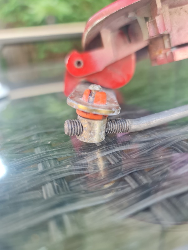

Great candidate for a part to become a 3D printed item.
[size=10pt]Mark[/size]
95 MGF
Last Edit:4 days 15 hours ago
by mowog73
Last edit: 4 days 15 hours ago by mowog73.
Please Log in or Create an account to join the conversation.


I like the amount of adjustment they give you.
Can adjust it perfectly.
Can adjust it perfectly.
by TA22GT
Please Log in or Create an account to join the conversation.


Smaller items are not that suitable for 3d printing in my experience, i have been working on a replacement fuel filler cap part, and even though I have reinforced the clips, they still break far too often. I think for things like this, it would be better to take a mould of one, and cast it, as I think the properties would be better.
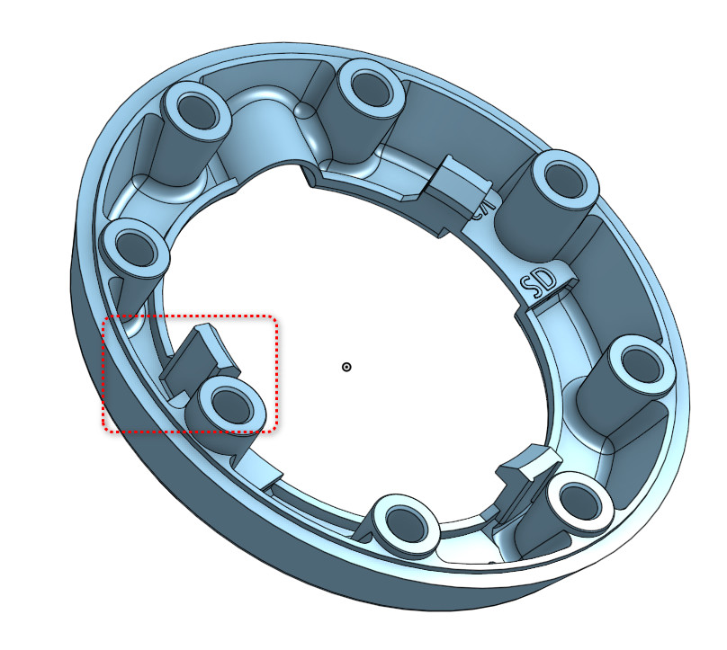
I should also add that orientation plays a big part, as printed parts effectively have a grain by the way the layers are built up, so ideally they should be printed at an angle or so the grain runs longitudinally.
I should also add that orientation plays a big part, as printed parts effectively have a grain by the way the layers are built up, so ideally they should be printed at an angle or so the grain runs longitudinally.
Last Edit:4 days 13 hours ago
by Daedalus
Last edit: 4 days 13 hours ago by Daedalus.
Please Log in or Create an account to join the conversation.
Time to create page: 0.493 seconds