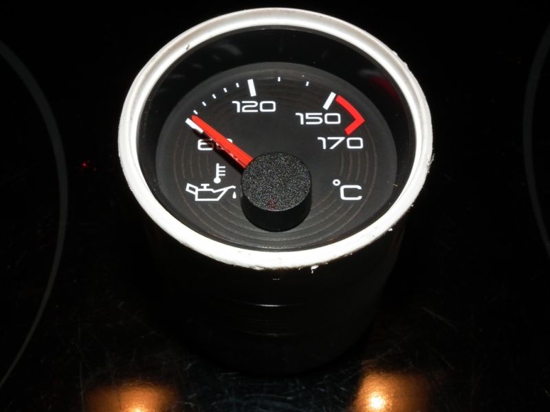
Fixing an LE 500 oil temperature gauge
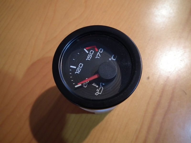
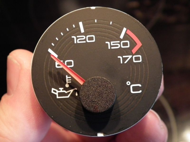
The problem was that the oil gauge stopped working and even went negative when the ignition was switched on as you can see here.
While the new TF is supposed to be less prone to head gasket failure, anyone who has an F/TF will know how important a gauge that is to make sure you don’t pile the revs on until the oil has reached a decent working temperature.
So, I decided to remove the LE 500 gauge and use a TF one that was donated to me to cobble 2 together and make a working one with the LE 500 look.
The first thing to do is remove the centre console. There is a how to on this, but be careful as you can damage it if you are too heavy handed.
http://www.the-t-bar.com/en/forum/22-cjj-s-guides/5155-centre-console-how-to-remove
I find the easiest way is to remove the centre vent and then you can apply pressure from behind the console. You can also disconnect the 2 gauges and head unit from here.
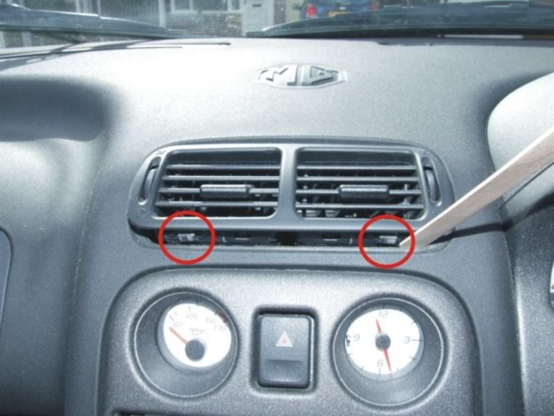
You need to locate each clip (5 in total) from the inside and use a screwdriver to push the little arm in the centre of the clip which will release it from the main dash.

Once the console is out you need to undo 4 screws that secure a frame which hold the 2 gauges in place.

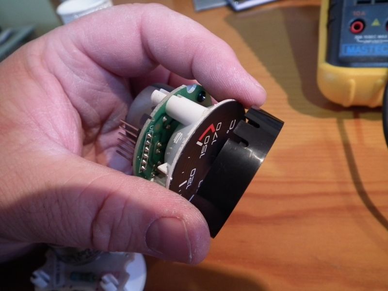
You should now be left holding the inner frame with 2 gauges in it.
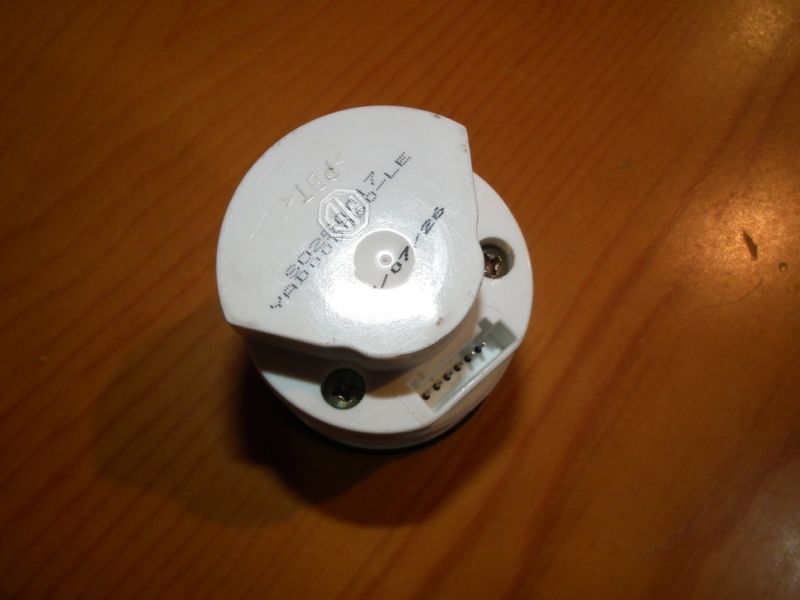
The oil gauge should just push out as it is only held in place by a rubber o-ring.
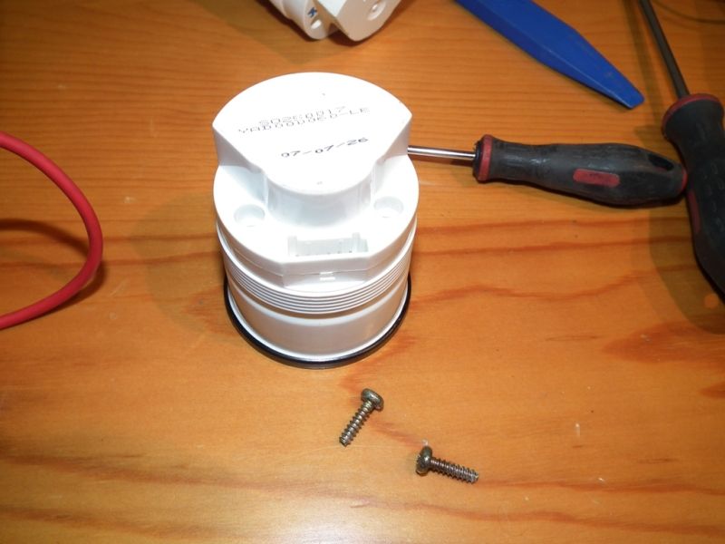
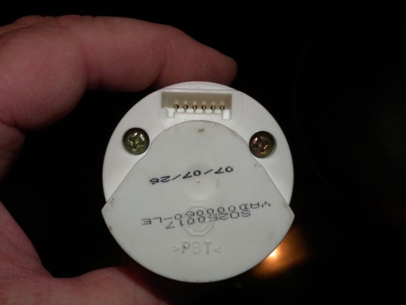
You now need to remove the 2 cross head screws (Torx on the earlier TF one).
Now you need to remove the front bezel/trim from the gauge. Using a small flat bladed screwdriver, force it under the inner edge of the ring. The black ring is brass painted black, and it is also reasonably soft, so take your time and be careful. Also be careful not to stab your hand with the screwdriver if it slips off the gauge.
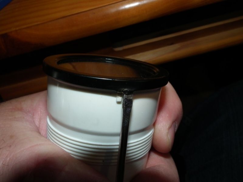
Now slightly twist the screwdriver repeatedly while applying sideways pressure with your other hand. The idea is to work around the edge, easing it up slightly. You should only need to do about a third or the way around to give enough to lever the black ring off. The main things to watch out for are not to mark the outside face of the ring or distort/crease it. You can make a bit of a mess with the inside as you won’t see it, but obviously try to be as neat as possible.
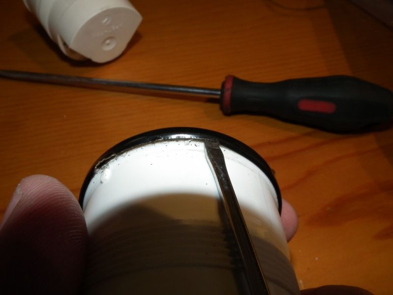
Once you have enough of the edge turned over you should be able to lever the ring off and work your way round until it pops off. Again, be careful not to mark the visible part.
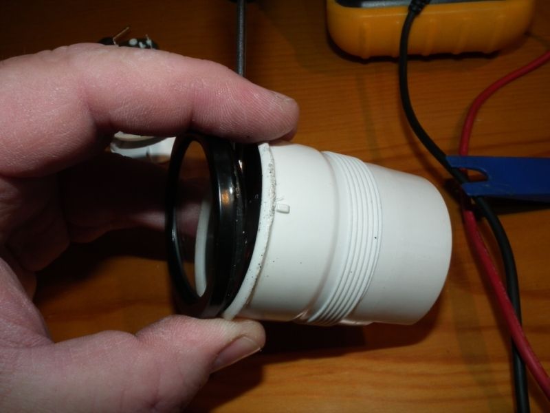
Now put the ring and glass somewhere safe.
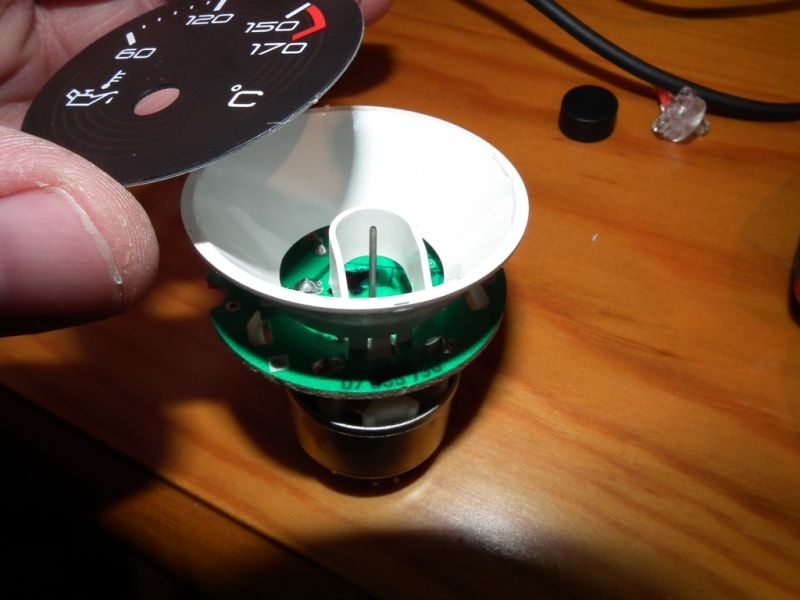
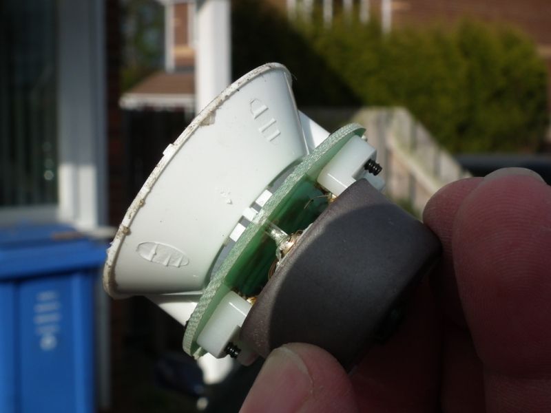
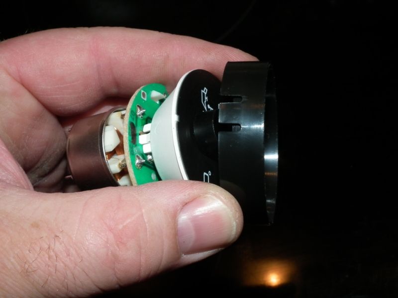
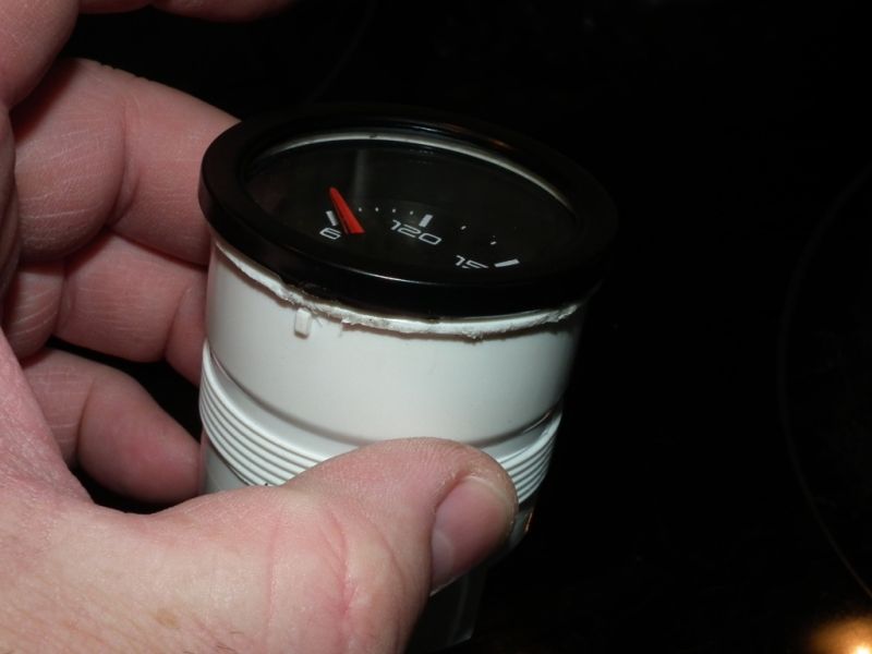
The inside part of the gauge should now slide out of the white housing.
Unclip the black trim bezel at the three points and remove. Put in a safe place.
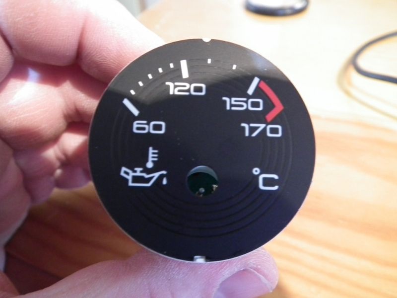
Now comes the difficult bit, removing the needle. It isn’t really difficult, but if you aren’t careful you could mark or damage the face of the dial.
I split a post-it note and fed it under the pointer to protect the face (don’t use the sticky bit as it could mark the face). Next you need 2 levers. One to place under one side of the centre point to lever against, and the other to insert under the centre point to actually lever against. Simply levering on one side can bend the spindle and takes a lot more force.
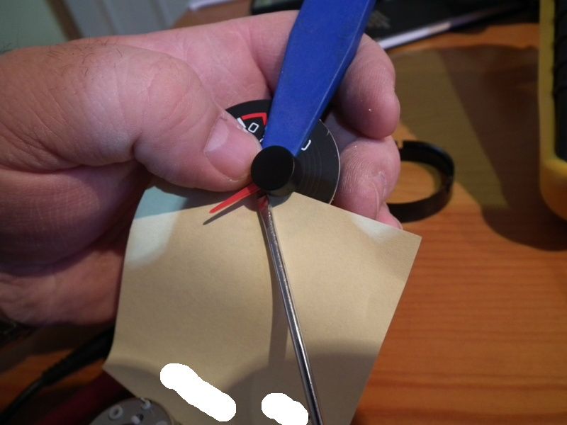
The needle is only pressed on during manufacture, so it WILL lever off. Be careful as it may fly off and make a note of where it is pointing as it can go back on in any position.
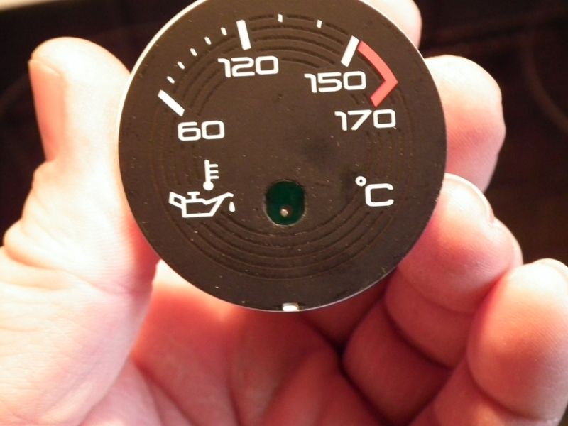
Next, use a craft knife and gently ease it under the edge of the black face. Now run it around to release it. It is stuck on around the edge so will come off fairly easy.
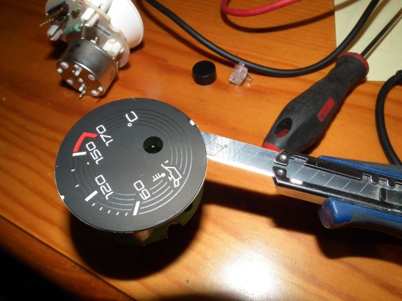
Once you have loosened enough of the edge you should be able to pull the face off. Store carefully, face down as the edge may be sticky.
That is the gauge stripped down. You need to do the same to the older TF gauge too, which is exactly the same sequence.
I had to strip down a little further as the LED illumination on the old gauge was red and the LE one was orange.
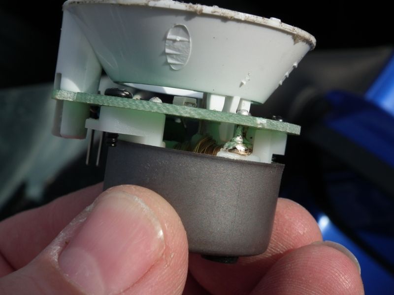
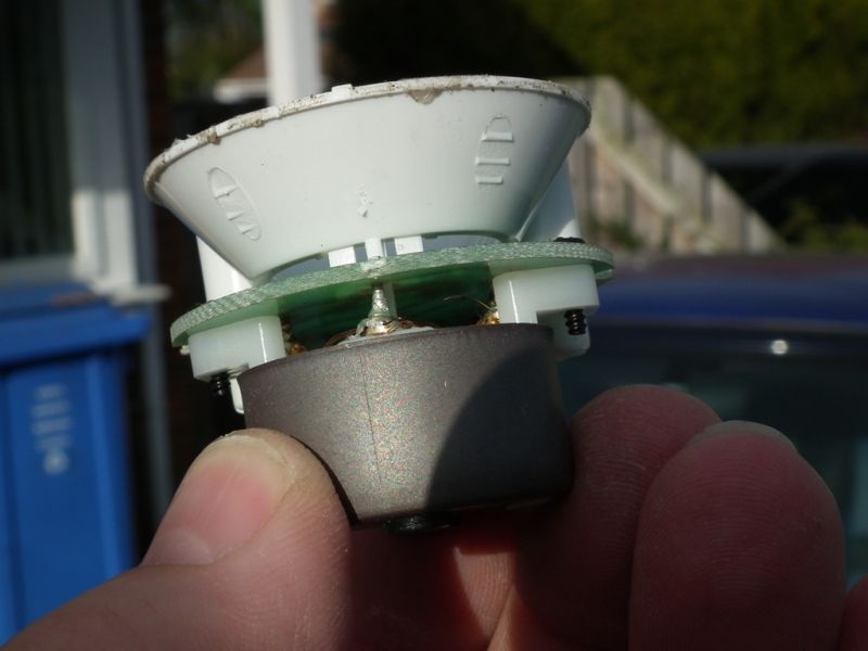
So, next to come off was the white plastic cowl. This was held on by one plastic clip and two plastic legs which clipped into the circuit board. These just squeeze together to release.
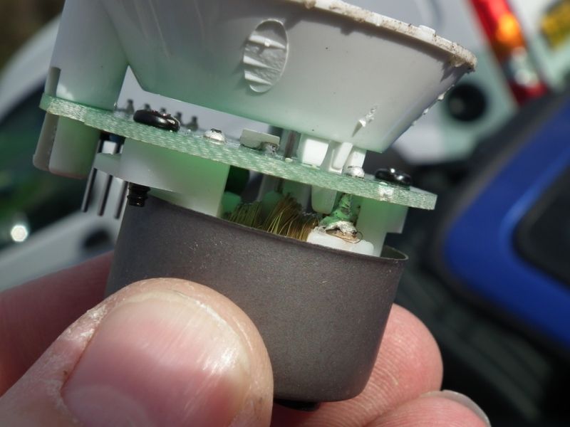
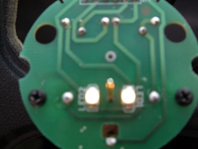
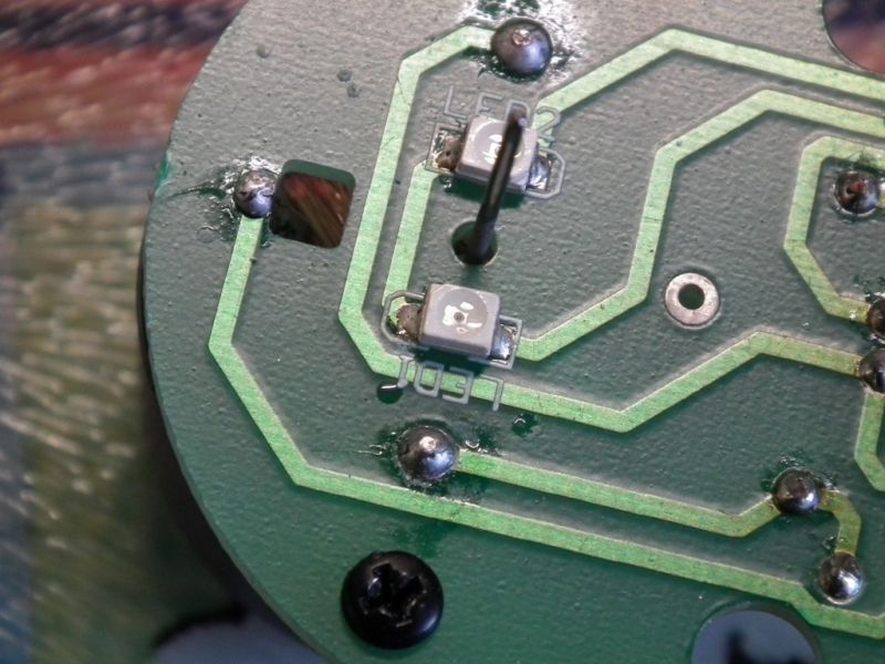
This exposes the circuit board. Here you can see the two different colours. They are blurred on purpose as you can see the colours better.
The old (Red)
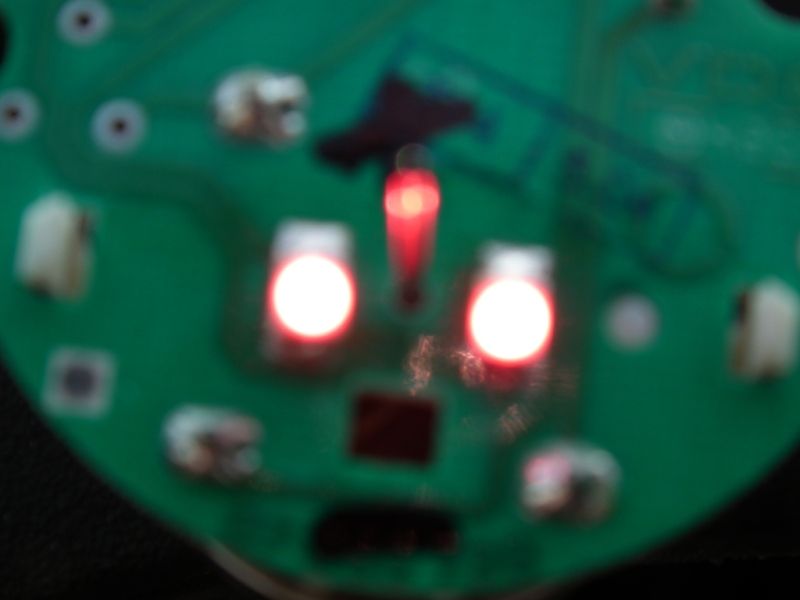
And the new (orange)
Anyone recognise their handy work?
Next job was do de solder the LEDs and swap them over. A bit fiddly, but just a case of melting the solder either side of each LED. They are very small and fiddly though.
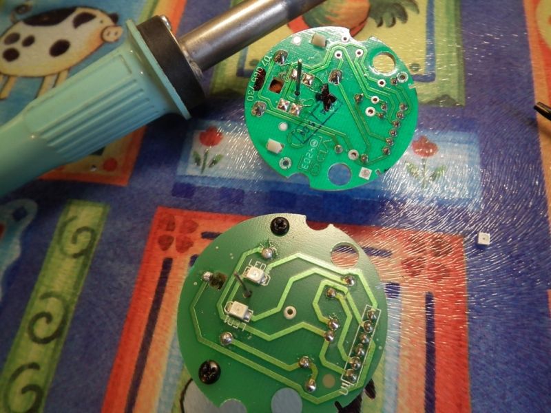
One mistake I did make was I took the LEDs off the LE 500 circuit board and fitted them to the old TF one the same way around. THIS WAS WRONG.
If you look at the old TF one, the + comes down from one of the resistors, to the top of the left LED, then from the bottom of that LED to the top of the right LED. It then goes from the bottom of the right LED back to the first terminal pin on the plug. This means that the + is the top of both LEDs.
The LE 500 one, however, is routed differently.
The + comes from the resistor, to the top of the RIGHT LED, from the bottom of the right LED to the bottom of the left LED and then from the top of the left LED back to the first pin. This means that the bottom of the right LED is + and the top of the left LED is +
As the LEDs are wired in series, if either, or both LEDs are soldered in the wrong way round then neither will work.
So after correcting my mistake, all was well.
Try it in the car to make sure the LEDs work before you put it back together.
Now refit the white plastic cowl which simply clips back into place on the circuit board. You can’t get it the wrong way round.
Now comes the next slight problem. Using the innards of the old gauge shows up another different. The spindle from the servo motor is slightly lower on the older gauge than the LE 500 item.
This means that the hole in the face is slightly in the wrong place. If the spindle/pointer body fouls on here then the gauge will stick and won’t work properly.
I used a small needle file to slightly elongate the bottom of the whole.
The face should still be sticky enough that it will refit easily. Note the notches in the face line up with the pegs in the cowl.
Next comes the needle.
This is the second problem. The spindle of the LE 500 servo motor is slightly thinner than the TF one, so it would take a lot of force to push the LE needle onto the thicker TF spindle. I opted to use the TF needle. There is no real difference in looks.
Simply line up the needle where you want it and push on.
Try pushing it on lightly first and checking it comes to rest where you want it to (about 10mm below the 60 mark)
Remember that this is just an indication and is not calibrated, so it isn’t too important as long as you fit it where YOU want it and learn how it reads later in your car.
Push the needle down the spindle until there is only a small gap left. If you push it too far then the needle will foul on the face and will not work. Test it by using your finger to move the needle up the scale and letting go. It should return to its resting position freely. If it sticks you may need to lever it off and start again.
Now, if everything is working fine, refit the black clip on bezel. It isn’t keyed, so can go on however you want it to.
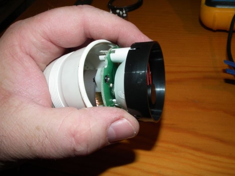
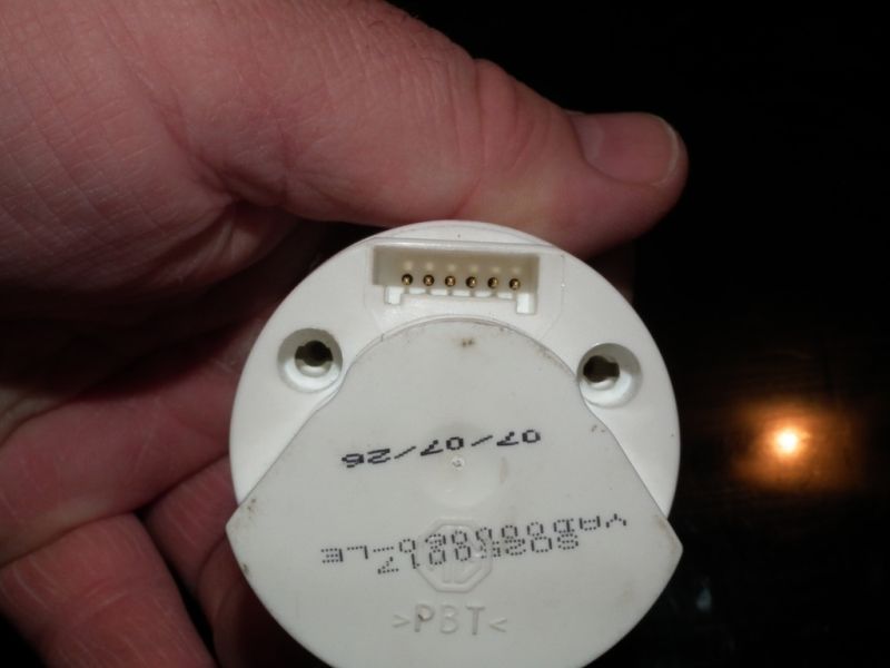
Next, feed the inner workings back into the casing so that the 5 pins feed through the 5 holes. It is easiest to have a bright light above and look down trying to line up the 2 screw holes with the inner screw holes.
And refit the 2 screws that hold the mechanism in place.
Now we need to refit the glass and retaining ring.
Hook as much of the ring around the lip as you can and work the rest on.
Now push from the front until it all clicks into place, then go around the back flattening the metal ring back down where you levered it out at the beginning.
You have now finished assembling the gauge.
Now, simply refit the gauge back into the centre console, refit the console and take the car for a test drive to see if it all works.
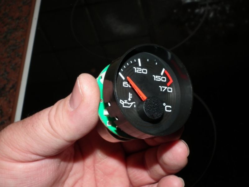
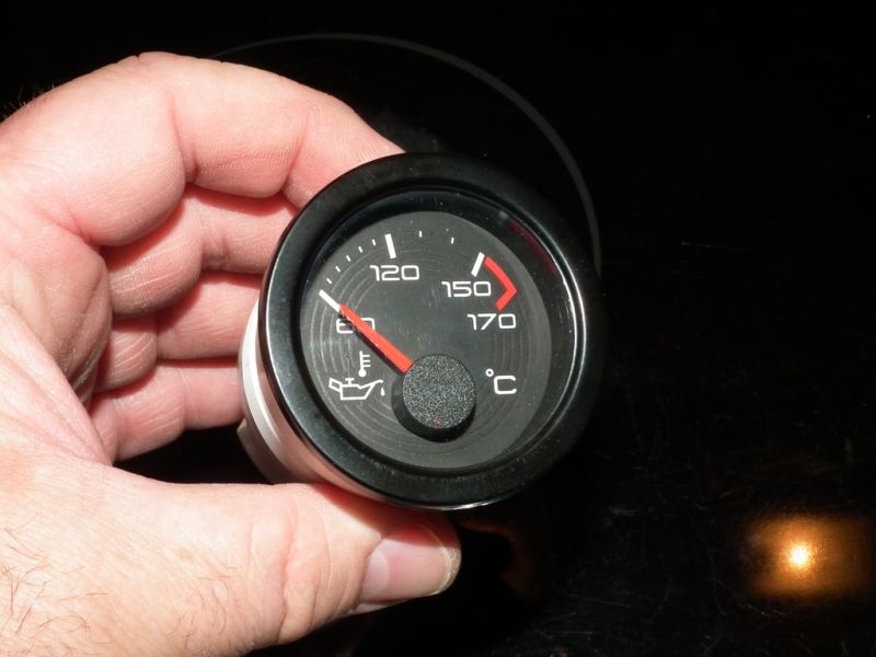
Thankfully, mine was a success and I now have a working “LE 500” dial.
Please Log in or Create an account to join the conversation.
Replied by PQD44 on topic Re: Fixing an LE 500 oil temperature gauge
Posted 14 years 3 months ago #45630
Just a pity MG don't see fit to provide the back up to buyers


Please Log in or Create an account to join the conversation.
- a Guest
- User
-

Public
- Thanks: 0
Replied by a Guest on topic Re: Fixing an LE 500 oil temperature gauge
Posted 14 years 3 months ago #45631
Great how too

Please Log in or Create an account to join the conversation.
Replied by cjj on topic Re: Fixing an LE 500 oil temperature gauge
Posted 14 years 3 months ago #45633I did on DeepBlue, so that the oil gauge was on the left rather than the right.
It's fairly straight forward.
Please Log in or Create an account to join the conversation.
Replied by PQD44 on topic Re: Fixing an LE 500 oil temperature gauge
Posted 14 years 3 months ago #45634Please Log in or Create an account to join the conversation.
- a Guest
- User
-
Public
- Thanks: 0
Replied by a Guest on topic Re: Fixing an LE 500 oil temperature gauge
Posted 14 years 3 months ago #45636 Please Log in or Create an account to join the conversation.
Replied by bensewell on topic Re: Fixing an LE 500 oil temperature gauge
Posted 14 years 3 months ago #45639Please Log in or Create an account to join the conversation.
Replied by cjj on topic Re: Fixing an LE 500 oil temperature gauge
Posted 14 years 3 months ago #45756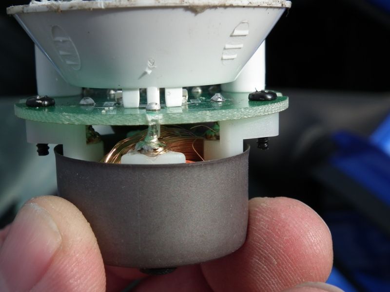
I am honestly shocked that these would pass quality control of any company, but I guess they didn’t expect anyone to see it.
Please Log in or Create an account to join the conversation.
- David Aiketgate
-
 Offline
- David
-

Super Users
- mgf mk2 freestyle mpi 16" wheels, in Anthracite.
- Posts: 20627
- Thanks: 4583
Replied by David Aiketgate on topic Re: Fixing an LE 500 oil temperature gauge
Posted 14 years 3 months ago #45757
David

Please Log in or Create an account to join the conversation.
Replied by mgfmad on topic Re: Fixing an LE 500 oil temperature gauge
Posted 14 years 3 months ago #45766
MG TF LE500 27 of 500
Please Log in or Create an account to join the conversation.
- Mr Forgetful
-
 Offline
- Qualified MGer
-

Registered
- I may be old but I'm not senile.
- Posts: 503
- Thanks: 195
Replied by Mr Forgetful on topic Re: Fixing an LE 500 oil temperature gauge
Posted 14 years 3 months ago #45768 
I may be old but I’m not senile:-
It’s just that I can’t remember whether it’s Alzheimer’s or Amnesia
Please Log in or Create an account to join the conversation.
- bryan young
-
 Offline
- Master MGer
-

Registered
- Posts: 3635
- Thanks: 776
Replied by bryan young on topic Re: Fixing an LE 500 oil temperature gauge
Posted 14 years 3 months ago #45807Great "how to" Clive, thank you.
Please Log in or Create an account to join the conversation.