Emerald ECU on MGF VVC mems 1/ 2 - How to Install.
- rough luck
-
 Offline
Topic Author
Offline
Topic Author
- Site Sponsor
-

Registered
- Jon
- Posts: 562
- Thanks: 67
Emerald ECU on MGF VVC mems 1/ 2 - How to Install. was created by rough luck
Posted 15 years 8 months ago #18714By far an away the most popular after market ECU for the MGF is the Emerald K3
This is because it copes with the VVC unit on the K-series and allows infinate tweaking
It can also flick between any one of three maps at the flick of dash switch, even while on the move
Right the tech spec: Emerald's site K3 page
Price: Although the site does give a price of £580, please remember this is ex vat, buy the time you add delivery and little extra's like Serial/USB adapter you will be somewhere around £725-£750
There are other slightly cheaper alternatives such as the DTA ECU but I beleive this has a few less features, one being the map switching
Additions you may want to think about putting in at the same time is a wideband Lambda sensor
The difference between a standard manufacturer NarrowBand and a Wideband, is quite simple,
Narrow band lambda sensors really only have 3 sensor outputs, 1) running lean, 2) running ok, 3) running rich
these sensors operate on a 0-1v output, the negative going to pin 18 on the emerald and the posative going to pin 7, pin 7 on the emerald is the only pin that the ECU looks to if narrowband is selected and the ECU times the input by 5 to give a basic reading
wideband lambda sensors normally operate on a 0-5v output however if required this can be adjusted
the sensor's ability to measure AFR (AIR FUEL RATIO) is far greater than the standard narrowband
This range can be adjusted but normally your looking at a range from 8.0-19.0 and rise or lower in 0.1 increments, the target your looking for is around 14.7 on unleaded fuel, if the wideband is of any quality it will have its own system to control the heating element within the sensor
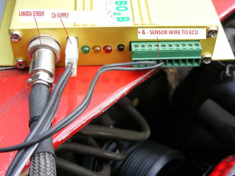
Installing the wideband lambda, disconnect the narrowband from the cars loom and replace the sensor with your new one, if the unit requires power on an ignition switched basis, use pin 28 on the emerald this is the main supply for engine relays, negative should be to a good body earth point, your output sensor wire + should go to pin 35 on the emerald, and output negative to pin 18 on the emerald
SETTING TO CHANGE: to change the settings to wideband on the "Ignition MAP" "CLOSED LOOP SETTINGS"
Also: "ECU Configuration tab", "AFR LAMBDA INPUT" you will need to tell the ECU to look to pin 35 from the drop down and enter in your VOLTS v's AFR ratio's these should be supplied by the supplier of the wideband as standard settings, i.e. 1.00v - 11.0 AFR, 2.00v - 13.0 AFR
If you wish to estimate the AFR values then as a rule of thumb, times the volts by 2 and add 9
Widebands range in price from about £150 upwards, in dash gauges are an option and come as either digital or analog with various controls for showing lambda or AFR and data logging, with pro systems starting about £400, these are the ones which should have data logging features and mulitple other sensor inputs such as exhaust gas temp etc
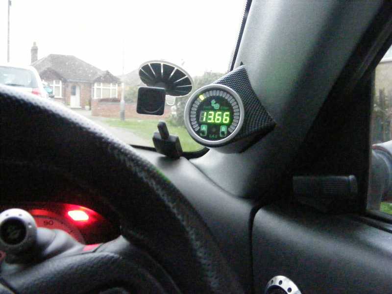
LA1 installed with a cheap ebay gauge pod:
Installing the Emerald ECU:
What can you get done before it arrives, not a lot apart from trying to work your way through the manual and get a feel for the software, Emerald will send this to you via the net, once downloaded install it and put a copy on CD for safe keeping
You will also be sent a config file, this should be loaded first as the file tells the ECU what all its outputs and inputs are and basically what engine is
When ordering the ECU you will be asked for a ruff engine upgrade spec of your car, this will allow them to send a basic map for you to at least get the car running
Your now down to getting it fitted:
wiring map:
All pin references are taken from the back looking at the wires, what you see on the attached wiring file is first a pic of the back of a socket, this allows you to see all pins numbers on all three sockets (1xEmerald 2xStandard ECU)
The next page shows the standard output/inputs of the Emerald before the config file is installed, the right hand collum shows the Emerald after the config file is loaded, so the righthand collum is what you are working to
The next two pages show the two sockets of the standard ECU, The left collum on each page shows the standard wire postions, the right hand side shows where on the Emerald socket they should be moved too
Remove your old ECU, and unclip the carbon canister allowing it to drop clear of the area you'll be working in
The Emerald comes with a male connector to plug in to the ECU (Emerald), I dont know if its by chance or what but the terminals in the standard ECU once removed fit in to the Emerald Male connector
additional terminals are also supplied should you need them
You then simply follow the wiring sheet (File is attached) what you are basically doing is taking terminals from the two standard ECU Connectors, remove each wire/terminal in turn and place in to the position on the emerald connector, DO THIS ONE BY ONE, and double check after completed, in a couple of cases i.e. earth wires you will find the they are attached together and go in to a single emerald terminal
DOUBLE CHECK ALL WIRES AGAIN
If the emerald hasn't come preloaded with your config file and base map you will now have to connect your PC to the emerald, in the pack with the USB adaptor you'll find a small cd, you need to install this before connecting the ECU (its the driver for the adaptor)
To connect the ECU, use the supplied cable and plug in to the back of the unit, there are two connectors don't mix them up, one is for map switching, there is a third USB type but its not in use, its for later additions
the other end of the cable goes to the serial adapter then to you PC, switch your ignition on to position II, load the emerald software, select from the top options "communication" then "read map" if a map appears then Emerald have preloaded it for you,
If not there is a "setup" option for the config file and TPS sensor
then loaded your base map by "open file" and then "Program Map"
Either way follow the intial setup for standard setting such as the TPS (Throttle Position Sensor)
Your car is now ready to fire up, be aware you probabily won't have a tickover
Once started you will find the base map will by its nature make the car run very rich (cool) so as to not cause damage
Ideally now get the car rolling road tuned
ENABLING ADAPTIVE MAPPING
However if you wish to set it up yourself heres a good start on how to select Adaptive mode
If you check that your map has the closed loop setting done (it should have) make sure the fuel shut off isn't enabled (as this disables adaptive mapping), Now go to the "Injection Map" and select the tab "Feedback Mode" using the shift and arrow keys you can highlight multiple sections relating to load and revs, If you now use the - and + keys you can cycle between the modes you want i.e. "Open Loop" "Closed Loop" and "Adaptive" each mode has a colour and you can have all three on one map in defferent section if you require it, as a base setting its a good idea to use "Closed Loop" settings in a block from load sites 0-4 up to about 2000 rpm (Dark Green) set the rest of the map to "Adaptive" (Bright Green)
REMEMBER AFTER ALL CHANGES CLICK COMMUNICATE TAB AND PROGRAM ECU, THEN IGNITION OFF AND ON AGAIN
Now you have adaptive mode set to start, start the car and allow it to get up to temperature take the car for a drive about 10 miles or so it doesn't matter how much it just to get some readings
When you get back, hook it back on to your computer, select "Read All Maps" from the ECU next to the "Feedback Mode" is another tab, "AFR Corrections" remember then to "Read Map" or you won't see any corrections gathered while driving, they will appear in percentage terms, these are suggested fueling by the ECU to hit your AFR Targets, to put these in to use on your map, Highlight either individuals cells or the whole block, to apply the selected area right click and select apply, remember to now save your map and program it to the Emerald ECU
A very speedy guide but it is very simple, alot easier than I thought, but its one of those things that has massive complicated manuals, just take the steps one by one
O yeah you will have to enable your emobilser option as the emerald can still supply this original function should you want it
Youtube channel of mods an track pics
http://www.youtube.com/user/busternorris?feature=mhum
Website: http://www.roughluckracing.com/ MG Rover Mobile Repairs Nationwide and Western Europe
Please Log in or Create an account to join the conversation.
- David Aiketgate
-
 Offline
- David
-

Super Users
- mgf mk2 freestyle mpi 16" wheels, in Anthracite.
- Posts: 20627
- Thanks: 4583
Replied by David Aiketgate on topic Re: Install an Emerald ECU on an MGF VVC mems 1 or 2
Posted 15 years 8 months ago #18720Keep us abreast of how you are getting on with this kit.
")
David

Please Log in or Create an account to join the conversation.
- rough luck
-
Offline
Topic Author
- Site Sponsor
-
Registered
- Jon
- Posts: 562
- Thanks: 67
Replied by rough luck on topic Re: Install an Emerald ECU on an MGF VVC mems 1 or 2
Posted 15 years 8 months ago #18721and add a simple guide to adding a wideband lambda, I cant put the wiring up as it wont let me attach word docs
Youtube channel of mods an track pics
http://www.youtube.com/user/busternorris?feature=mhum
Website: http://www.roughluckracing.com/ MG Rover Mobile Repairs Nationwide and Western Europe
Please Log in or Create an account to join the conversation.
- David Aiketgate
-
Offline
- David
-
Super Users
- mgf mk2 freestyle mpi 16" wheels, in Anthracite.
- Posts: 20627
- Thanks: 4583
Replied by David Aiketgate on topic Re: Install an Emerald ECU on an MGF VVC mems 1 or 2
Posted 15 years 8 months ago #18739David
Please Log in or Create an account to join the conversation.
- David Aiketgate
-
Offline
- David
-
Super Users
- mgf mk2 freestyle mpi 16" wheels, in Anthracite.
- Posts: 20627
- Thanks: 4583
Replied by David Aiketgate on topic Re: Install an Emerald ECU on an MGF VVC mems 1 or 2
Posted 15 years 8 months ago #18741David
Please Log in or Create an account to join the conversation.
- rough luck
-
Offline
Topic Author
- Site Sponsor
-
Registered
- Jon
- Posts: 562
- Thanks: 67
Replied by rough luck on topic Re: Install an Emerald ECU on an MGF VVC mems 1 or 2
Posted 15 years 7 months ago #18834The gauge pod turned up today, I went for a cheap £10 one from ebay as I knew I'd be chopping it up to make it fit
So as soon as it was out of the packet the dremil came out an its all done
Youtube channel of mods an track pics
http://www.youtube.com/user/busternorris?feature=mhum
Website: http://www.roughluckracing.com/ MG Rover Mobile Repairs Nationwide and Western Europe
Please Log in or Create an account to join the conversation.
- rough luck
-
Offline
Topic Author
- Site Sponsor
-
Registered
- Jon
- Posts: 562
- Thanks: 67
Replied by rough luck on topic Re: Install an Emerald ECU on an MGF VVC mems 1 or 2
Posted 15 years 7 months ago #18859I've updated how to re-map the fuelling with adaptive mode which should come in handy if you cant afford a rolling road session striaght away
Youtube channel of mods an track pics
http://www.youtube.com/user/busternorris?feature=mhum
Website: http://www.roughluckracing.com/ MG Rover Mobile Repairs Nationwide and Western Europe
Please Log in or Create an account to join the conversation.
- David Aiketgate
-
Offline
- David
-
Super Users
- mgf mk2 freestyle mpi 16" wheels, in Anthracite.
- Posts: 20627
- Thanks: 4583
Replied by David Aiketgate on topic Re: Install an Emerald ECU on an MGF VVC mems 1 or 2
Posted 15 years 7 months ago #18861A really interesting read, and a few more piccies never go wrong.:lol:
David
Please Log in or Create an account to join the conversation.
- rough luck
-
Offline
Topic Author
- Site Sponsor
-
Registered
- Jon
- Posts: 562
- Thanks: 67
Replied by rough luck on topic Re: Install an Emerald ECU on an MGF VVC mems 1 or 2
Posted 15 years 4 months ago #21887I sort of promised a guide through the Emerald software and had forgot about it until I got an email today
So here you go, a page by page guide of the basic's
I’ll stay clear of the more in-depth menu’s but have pics of the menu functions for them
The pictures have been taken from several maps so in no way are a working map
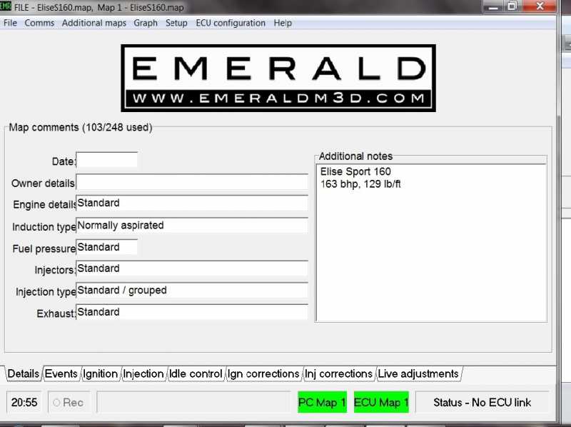
Once you have installed your Emerald in to the car you will have to load two files using the software, the first will be the Config file, this file basically tells the ECU its output and inputs or in even more basic terms what your car is
Use the “File” “Open” change the file type to .fig and open your Config file, Then from the “Comms” menu use the “Program” option to send the information to the ECU, Your cable must be connected and the ignition on position II be the software will connect
Next do the same with the base map supplied to you if you have one, the file type will be .map if its a newer version, remember to use the program option again, you may have to turn the ignition OFF and ON again for changes to take place, this applies to all changes in the future unless you are using the Live Update screen
The first shot is you information screen and home screen for the software, this will be filled in by the software if you read the map/maps from the ECU or have loaded a map from file, its your place to list any mods or tweaks to this individual map
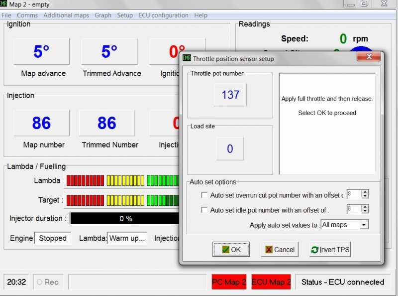
Set up your Throttle Sensor
From the main screen select the “Setup” the “Throttle Position Sensor”
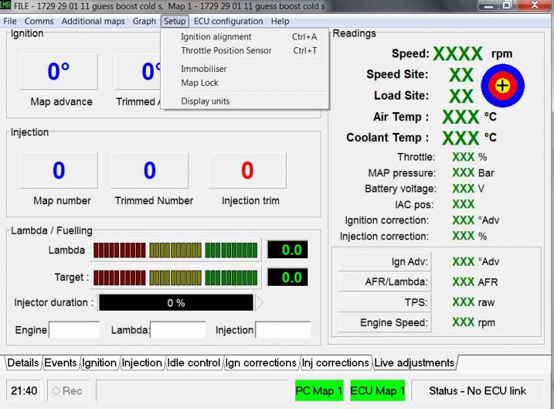
Follow the on screen instructions, its basically, press fully and release, then press OK
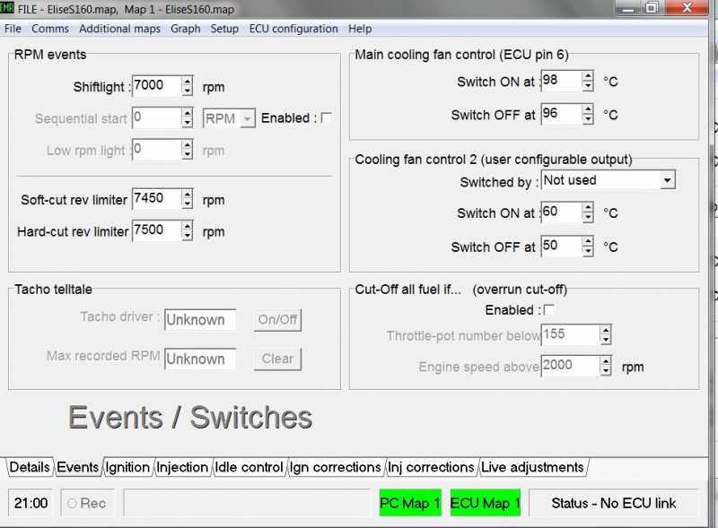
Events Map
This screen is your first but not often used screen for changes and settings
Some handy features over the standard ECU on this screen, If you require a gear change light on your dash to come on warning your near max rpm you can set the RPM for the light here,
Within the same section you have two more settings for RPM, the soft cut off for the max rpm and hard cut off (total max rpm at which the engine will cut out) So Yup you choose your own highest RPM, be aware the VVC unit will start falling to bits at about 7750rpm according to ZandF Tuning, although my last engine did like it before it went bang
Tachco telltale is always handy, with this active go for a spirited drive, once you have stopped and ignition off, turn the ignition back on the RPM needle with shoot straight up to its highest position from its last run
The other options on this screen are Cooling fan or fans (secondary could be an electric water pump)
And fuel cut offs
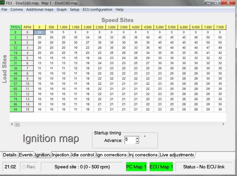
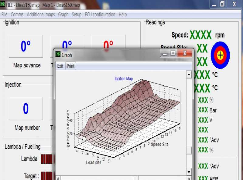
Ignition Map
The first of your most used map when you have it rolling roaded, down the left you will see the throttle position, these increments can be changed if require
Along the top you have RPM on the base maps this normally goes up in blocks of 500rpm’s
And an initial start up advance, this advance only hold for a few seconds
Map adjustments made here are not instant and need to be programmed to the ECU, however I have tested if you can program while the engine is still running/still connected and that’s fine, this makes it easier to adjust if you have an erratic idle, if you are trying to do it on the live screen it may be jumping around the speed or load sites very quickly and you may adjust the wrong area, so doing it here slows the process and allows you to get it right first time
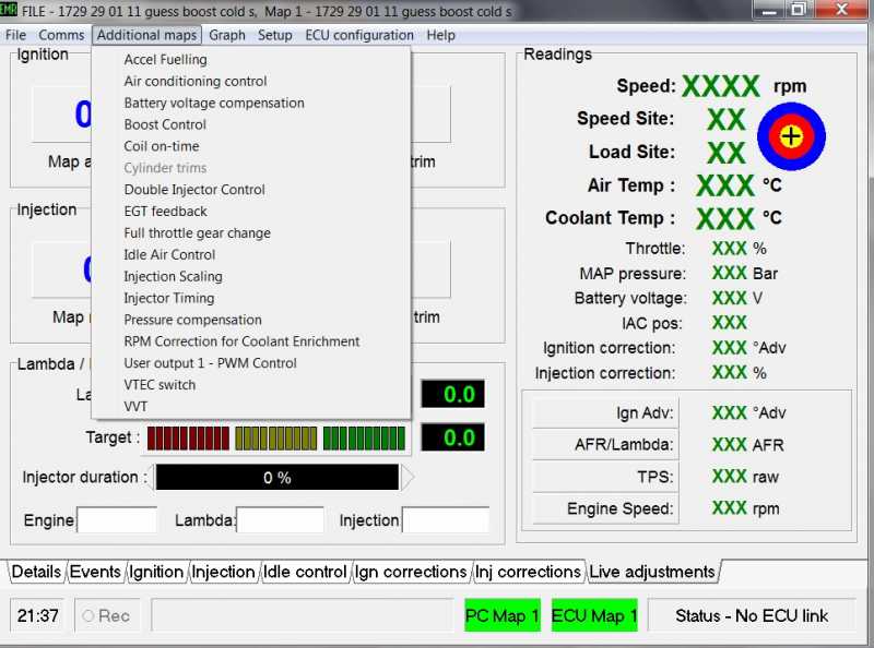
Injection Map
A more complex set of maps with sub tabs
The front map is set out just the same as the ignition map,
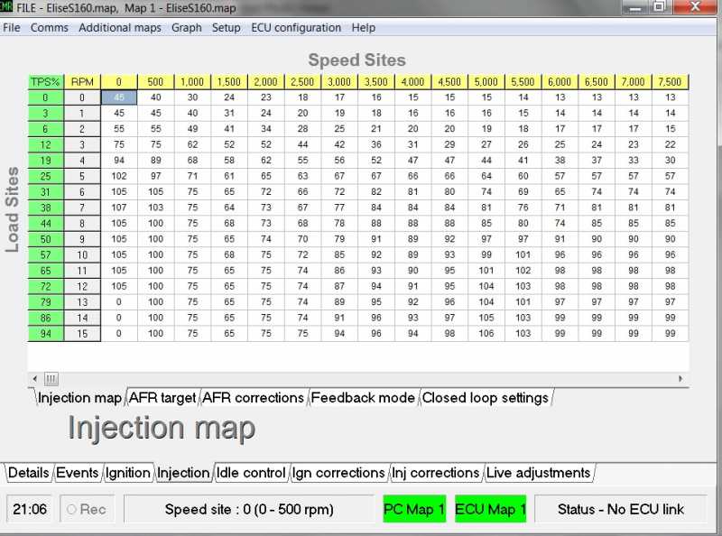
As mentioned in the ignition map the sites and loads can be changed to smooth out the running
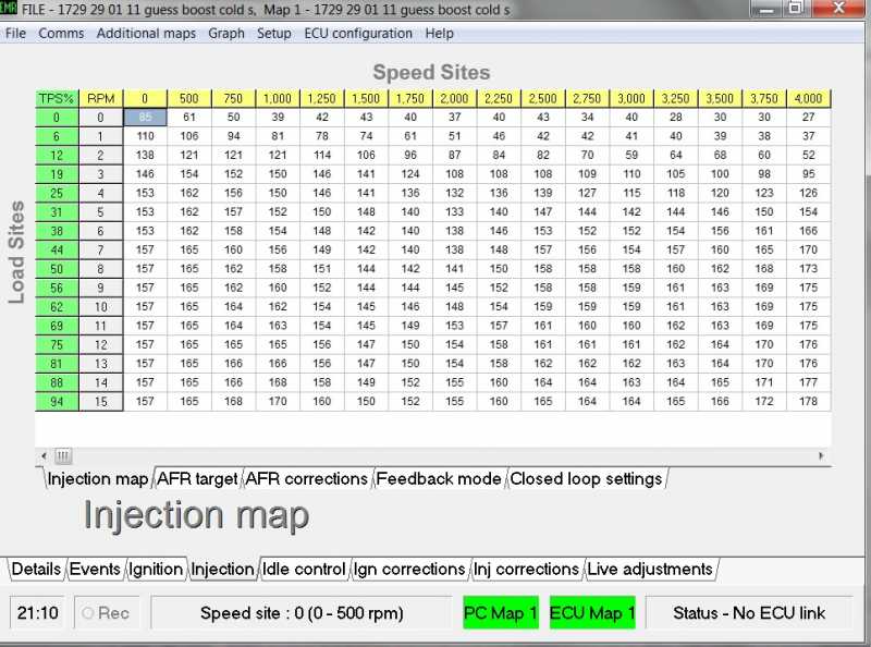
Below is a map were the RPM increments have been lowered from 500rpm block to 250rpm blocks, this isn’t as much of a pain to do as you think, once you have entered the new ranges the software gives you the option for it to work out all the new fuel settings based on what was there before, at the same time as it is doing this to the injection map, it also works out and changes the Ignition map to suit i.e. 500rpm to 250’s and all the timings on the map
Injection with 250rpm settings
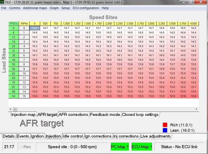
The next tab is the Air Fuel Ratio(AFR) targets, these targets relate to all positions on the ignition and injection maps and are used by the adaptive fuel mapping mode
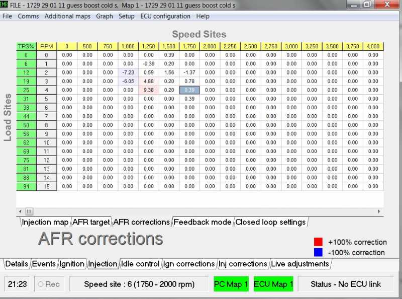
AFR Correction tab, depending on which modes you choose on the next tab (Feedback Mode), the ECU will work out while driving around where your engine is running rich or lean, It then calculates adjustment to be made to your Injection map and posts them here, The leaner the mixture the section of the map turns BLUE or richer it turns RED, by highlighting the individual blocks or selecting a whole area you can apply all or individual corrections by right clicking and applying
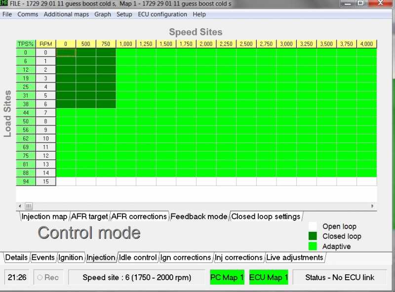
Feedback Mode is your next fuelling tab
You have three options to set your map up with, the most important for getting you up and running after installing the base map will be the adaptive mode, this is because generally base maps are very rich on fuel rather than lean, running lean creates much more heat and may cause damage, so your provider will bump up the fuel as a precaution, to change the section modes use the + or – keys to change the colours in the relevant area you wish to collect data on
Open Loop – white (Lambda signal is monitored by the ECU but not used)
Closed Loop – Dark Green (When closed loop conditions met, the ECU changes fuel etc to meet AFR Targets)
Adaptive – Bright Green (same as Closed Loop but corrections are stored to be applied permanently)
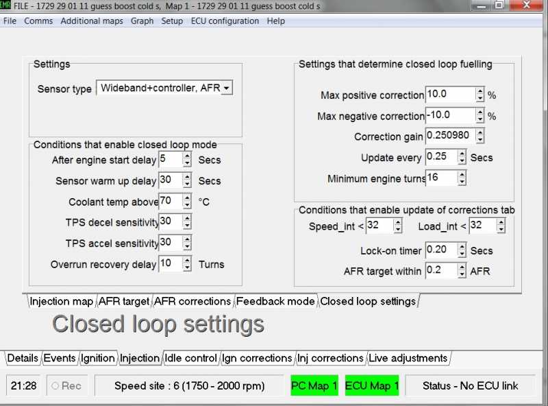
Closed Loop setting
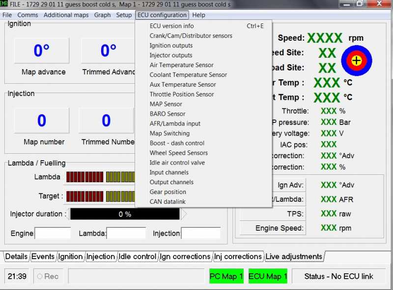
These setting tell the ECU when to start the above modes, and what sensors are attached
Speed int and Load int 32 are more easily seen on the Live update screen as a target, the centre is Yellow and where you are aiming for with the cross hairs, RED is within 32 and Blue within 64
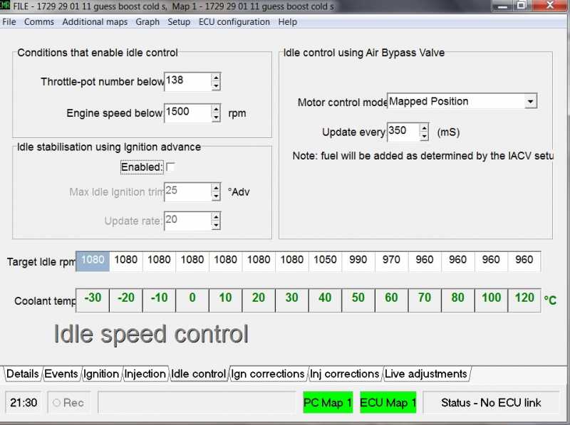
Idle Control is the next one and thank god this is getting easier
Target RPM’s relating to coolant temperature and when is the engine actually idling, although the IVAC/stepper motor does have separate temperature controlled settings and separate starting settings
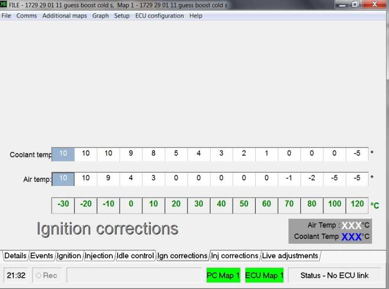
Ignition Corrections
Two lines of setting that both change ignition timing in 10 degrees blocks, so the people in the know say every 10 degrees colder than 20 degrees air temperature the engine should be advanced approx 3 degrees, with regard to coolant temperature there is a formula which only works once you have the engine running up at normal temp and ticking over nicely then you can work out the rest
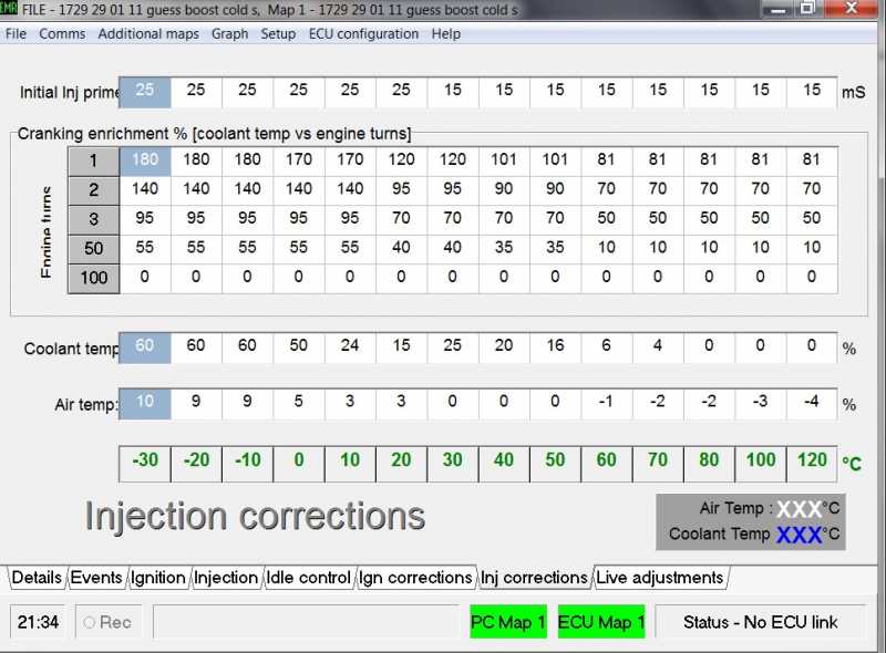
Injection Corrections
The bottom two are the same as the above section Ignition corrections but relate to fuel on this map
The middle section is also temperature related but to do with the initial starting of the car i.e. will it start off the key, if the car won’t start straight off try increasing these figures, don’t worry about being too accurate as these settings only last for a few seconds, you may find that the top section is not required, the top one is a one off prime only when the ignition is put to the start postion
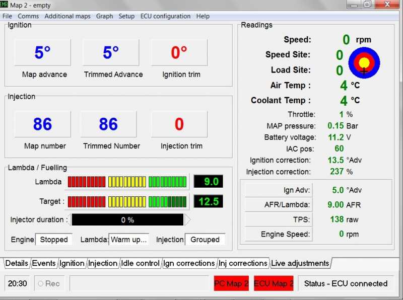
Live Update Screen
I’m sure you will have all seen these sort of screens in garages, from this screen you can make live adjustments and see the car react, these are not the only adjustable options on this screen others can be cycled through, adjustments can be made on a temporary basis until the results are known then accepted, the bottom right section is user defined from drop down lists
I’ve only touched on the basics
Here’s a few more pic’s of menu’s and graph plotting
Hopefully that has cut out some of the unknown, and will get a few people up and running
The actual manual is about 70 pages long and to be honest I found it amazing but very heavy reading at first, it’s the sort of manual you’re better off reading when you know the software rather than starting with it
Youtube channel of mods an track pics
http://www.youtube.com/user/busternorris?feature=mhum
Website: http://www.roughluckracing.com/ MG Rover Mobile Repairs Nationwide and Western Europe
Please Log in or Create an account to join the conversation.
- David Aiketgate
-
Offline
- David
-
Super Users
- mgf mk2 freestyle mpi 16" wheels, in Anthracite.
- Posts: 20627
- Thanks: 4583
Replied by David Aiketgate on topic Re: Emerald ECU on MGF VVC mems 1/ 2 - How to Install.
Posted 15 years 4 months ago #21890
A great post for those wanting to go down the emerald path!

David
Please Log in or Create an account to join the conversation.
- rough luck
-
Offline
Topic Author
- Site Sponsor
-
Registered
- Jon
- Posts: 562
- Thanks: 67
Replied by rough luck on topic Re: Emerald ECU on MGF VVC mems 1/ 2 - How to Install.
Posted 15 years 4 months ago #22006Once you have your gauge mount it where ever you like

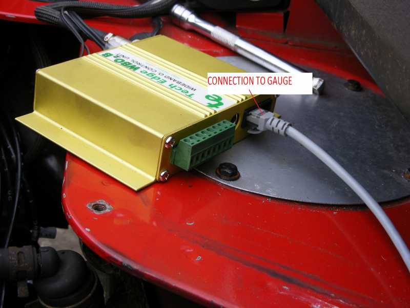
Take out your old lambda and replace with the wideband, they are the same size normally 22mm, make sure you route the cable away from moving parts and extreme heat, rather than 4 wires widebands tend to have more in this case 6
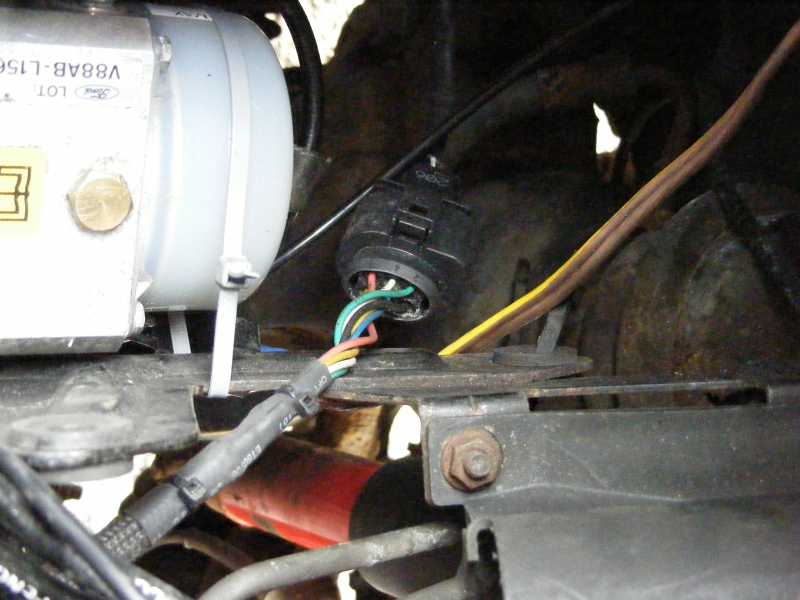
I wasn't sure how tough the data logging box was so mounted it on the back shelf in the car
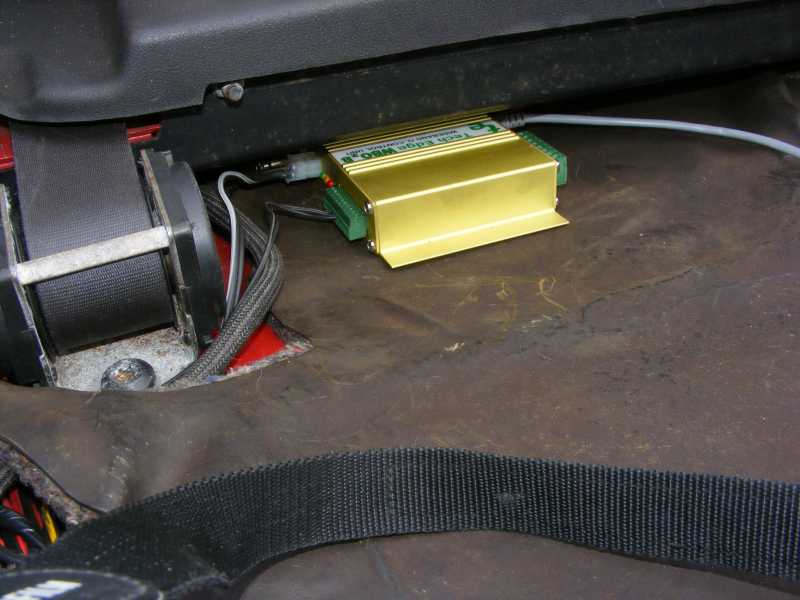
Wiring is easy and not even separate power was needed for the gauge
Thats it configure the ECU to wideband and your done, Cost of the above unit with gauge is about £450
Youtube channel of mods an track pics
http://www.youtube.com/user/busternorris?feature=mhum
Website: http://www.roughluckracing.com/ MG Rover Mobile Repairs Nationwide and Western Europe
Please Log in or Create an account to join the conversation.
- Leigh Ping
-
 Offline
- Moderator
-

Registered
- Posts: 6840
- Thanks: 1634
Replied by Leigh Ping on topic Re: Emerald ECU on MGF VVC mems 1/ 2 - How to Install.
Posted 14 years 6 months ago #35278MG Rover Mobile Repairs Nationwide and Western Europe
Please Log in or Create an account to join the conversation.