This is how I wired the ECU from a Rover 200 BRM. I had a quick look at the wiring diagram for a Mini MPI and I believe that it is the same.
Please check it for yourself though because I cannot accept liability if my information is wrong.
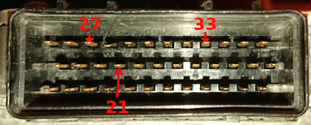
Looking at the ECU with black connector on the left and red connector on the right, and with the top plate (with a big X) facing up.
Black connector
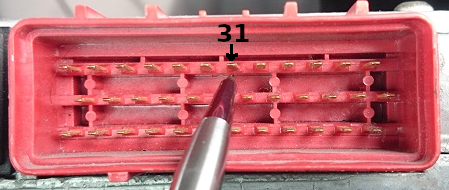
Red connector
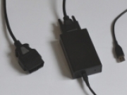
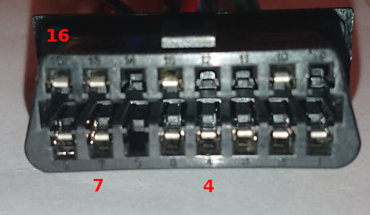
16 pin diagnostic connector
Black connector:-
21 (middle row, fourth pin from left): 0V
27 (top row, third pin from left): 12V
33 (top row, ninth pin from left): 12V
Red connector:-
31 (top row, seventh pin from left): K-line
Diagnostic socket:-
4: 0V
7: K-line
16: 12V
Please be careful !

") - and connected the Ecu, the Pscan and the battery.
- and connected the Ecu, the Pscan and the battery.