Due to the incredibly convoluted air intake system on the MGF Mk 1 it benefits greatly from the installation of a cold air induction system. This guide will show you how to install one of the most popular systems – the Pipercross Viper.
It is highly recommended that you change the original 48mm throttle body for the later alloy 52mm Dellorto part. This increases the airfolow through the throttle by 17% and makes a noticeable difference by itself. There a few online guides for this and I used this one:
Throttle body install
I would suggest doing this first and then resetting the baseline throttle position sensor reading in the engine management system by turning the ignition on (position II), and stamp on the throttle pedal five times in 20 seconds, and switch off. Once you are happy that this is working ok then the ‘fun’ begins.
I did quite a bit of reading on several forums regarding the positioning of the intake pipe and decided to route this to the passenger side air vent. Due to the resonance box in the Mk 1 F this is a more difficult option than routing the intake under the car. However, the under car position is, at speed, a field of negative pressure - that’s why car’s don’t fly (hopefully). Also there is a possibility of standing water being sucked into the intake (not good) as well as being another thing that can get damaged over speed humps etc.
I also wanted to do this as cheaply as possible so I bought a ‘nearly new’ Viper from eBay that was initially made for a Citroen. The only thing you have to be careful of is that you buy one that doesn’t have a small breather pipe coming out of the outlet pipe, as this is not required on the K series engine. Once I had bought the other bits I needed the whole lot came to just under £100.
Also this Viper’s outlet is 83mm (they are NOT all the same) and the connection to the throttle body is 70mm. I bought a reducer elbow to address this. I had to get an 80mm – 70mm but the 80mm end fits quite easily over the 83mm outlet from the Viper.
So here’s what I needed: Viper, 80mm – 70mm reducer elbow, alloy connector (70mm external), 70mm straight pipe, 76mm corrugated inlet pipe (1m), ram end, bracket and clips.
The first part of the installation is the removal of the original air filter box. Once again I found a good online guide. You only need to carry out steps 1 – 6.
Air filter box removal
Once all this was done I test fitted the pipes, to make sure everything looked ok. The red arrows mark the elbow reducer, alloy connector, straight pipe and the 52mm throttle body that I had already fitted and tested.
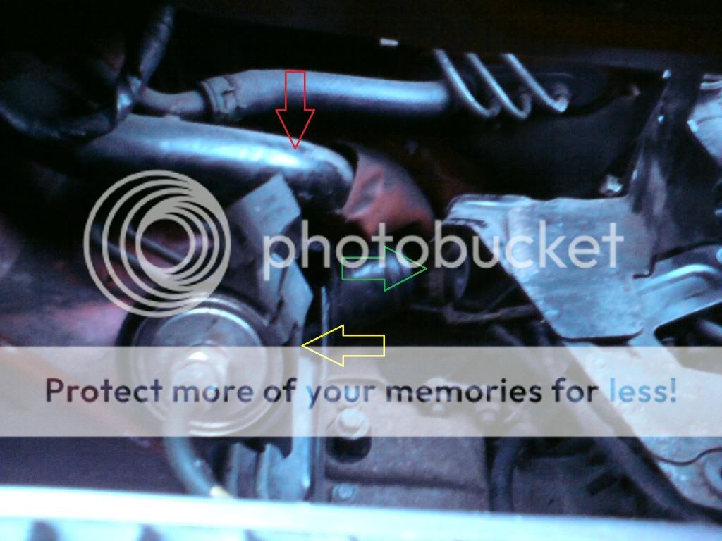
Here’s the view through the engine cover. Red arrow shows visible part of resonator box, green arrow is the air filter box bracket and yellow arrow shows 3 fixed pipes that obstruct the removal of 3 retaining screws for the air filter bracket.
It was at this point I tested that the 76mm inlet pipe would fit in the vent and then realised that it couldn’t get into the engine bay because of the resonator box!
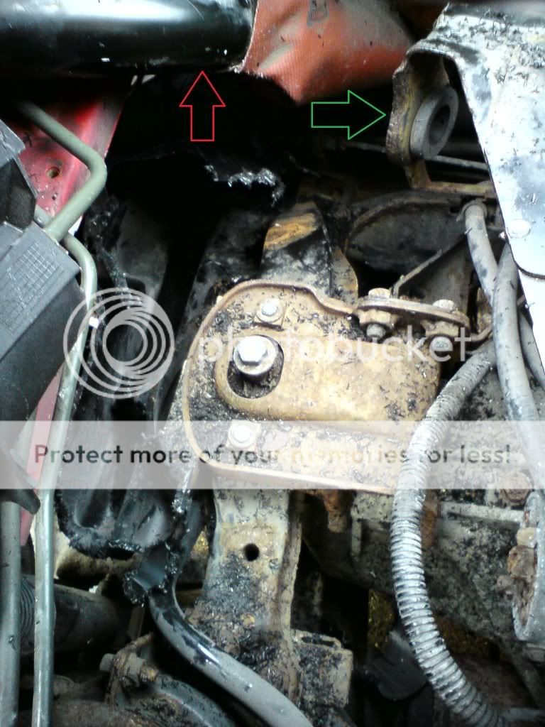
You have to unbolt the starter motor (yellow arrow) and then remove the 3 bolts on the Air filter box bracket, which are under the 3 pipes on the left shown in image 2. The end of the bracket closest to the engine has a connector that holds 3 pipes. I had problems removing all these so opted for sliding the left hand edge of the bracket from under the 3 pipes and then moving the bracket through 90 degrees so that it was laying against the engine. The green arrow shows the same part of the bracket that you can compare to image 2 to see what I mean. I now realised that the part of the large resonator box that had to come out is underneath the fuel filler pipe (red arrow).
The only way to get the resonator box out is either to drop the subframe, which certainly wasn’t an option, or to cut it out, piece by piece in situ. Obviously, you need to be very careful when cutting near the filler pipe. I cut away as much as I safely could then realised it would be impossible to get to all the front section, so decided to remove the back section and try to pull it out. Here’s what it looked like after cutting away the top and back of the resonator box. Again the filler is the red arrow and the bracket is the green arrow. There are 2 retaining bolts that attach the box to the wheel arch. The bolts are visible when you look from the outside into the wheel arch, but I couldn’t get them out, so I managed to free them by cutting the box from the inside.
Here’s a side on view once this had been completed (red and green arrows as before) a large part of the box has now been removed and the remaining part of the box was loose but still too big to pull out.
A bit more cutting and pulling and voila! You can now see what a large area the resonator box takes up! Under the fuel filler pipe you can now see light coming in through the air vent into the engine bay.
As the car was outside and it was really cold this work was done over 2 days. I would estimate an expert with a dremel (this was my first time using one) would do the job a lot quicker than me but it would still be a couple of hours work. I threw away the bits I cut out the first day but here’s what came out on day 2!
Now screw the filter box bracket back in place and bolt the starter motor back on. The Yellow arrow shows where to attach the Viper bracket.
I had a problem that when I test fitted the Viper unit - the outlet pipe was way too long, After calculating how much had to come off I marked the pipe and placed an elastic band around to act as a guide. If you have to do this then stuff a paper towel into the pipe PAST where you are going to cut and keep this pipe facing downwards when you cut it – this ensures that any particles do not fall into the filter. I cut mine quite easily with a small hacksaw and then smoothed the edge with sandpaper. I then cleaned any debris from the inside and THEN removed the paper towel – keeping the pipe facing down at al times.
As my second hand unit came with the retaining bracket it just required 2 linked jubilee clips around the unit to attach it to the point on the air filter box bracket shown previously. With the 90 degree elbow and the alloy connector between the 2 pipes it is easy to line this all up perfectly. Note: this couldn’t be achieved using a 45 degree elbow.
Here’s the install looking from the back of the car. As you can see I was a jubilee clip short because of having to use 2 for the Viper unit.
Another view through the engine cover, note that the Viper is pointing downwards towards the air vent (in the ideal position) when attached to the air filter box bracket. The rigidity of the corrugated inlet pipe, over more flexible pipes, really helps here as you can shape it to fit without the need of fixing it. I am sure that some installs using more flexible pipe will have points which are almost certainly pinched because of their construction.

Now for the vent, remove the 2 screws that hold the facing on. With the corrugated flexi pipe it was necessary to then remove the other 3 screws that hold in the plastic ring and the longer collar part behind it. Once these were out I had to cut away the back part of the innermost plastic collar to allow the flexi pipe to pass through it freely. As I referred to previously a more pliable pipe would get constricted at this point, which would reduce airflow. Screw the 2 plastic parts back in and attach the ram end to the pipe. Push the pipe so that the ram end is all the way back to allow the facing to screw back on properly.
Refit the facing and you’re done! I used a black flexi pipe and ram end so that it is fairly inconspicuous behind the black mesh of the vent.
Just to surmise a few points.
Use a 90 degree elbow pipe with alloy connector to allow attaching the Viper to the existing air filter bracket securely.
Corrugated flexi pipe ensures no constriction and is easier to fix in place.
Side vent is, in most people’s opinion, better that underneath. It’s a lot more work on the Mk 1 but well worth it, in my opinion.
You now have to reset the baseline throttle position sensor reading in the engine management system by turning the ignition on (position II), and stamp on the throttle pedal five times in 20 seconds, and switch off. You will notice the change in engine note immediately.
Once that’s done take it for a drive and try to get the stupid grin off your face (absolutely no chance!)


")


")


 Russell has said he will do it for me though along with my 52mm throttle body